Basic Introduction to ASME B16.5 Flanges

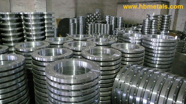
What are ASME B16.5 flanges

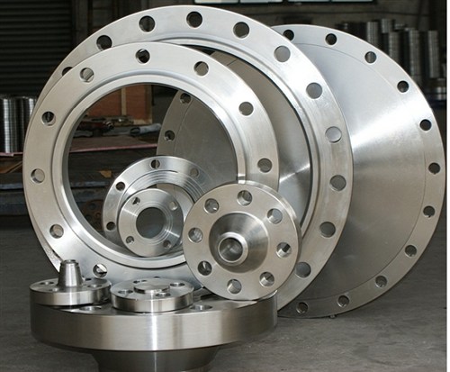
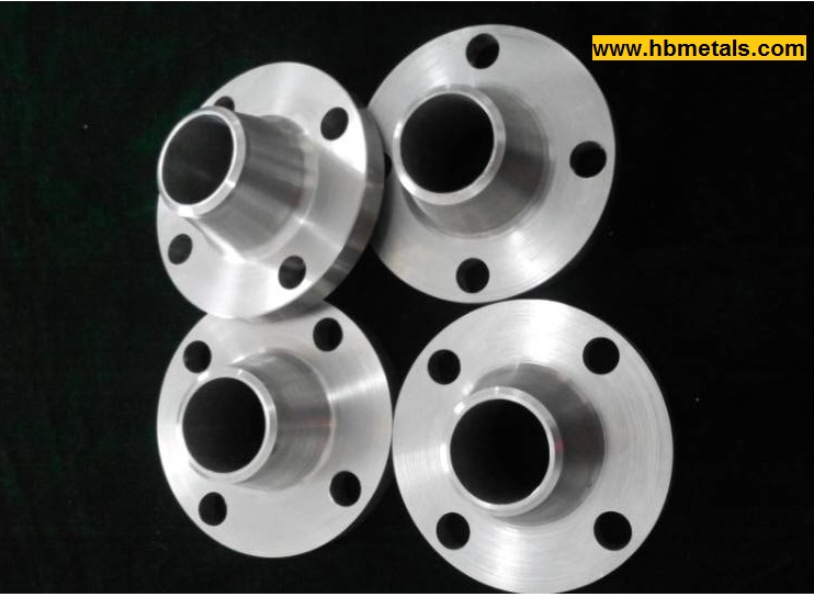
ASME B16.5 is the standard specification for pipe flanges and flanged fittings from NPS 1/2 (1/2″) through NPS 24 (24″) covering materials, pressure-temperature ratings, dimensions, tolerances, marking & packaging, and testing methods. ASME B16.5 flanges are designated into seven pressure ratings including Class 150, 300, 400, 600, 900 and 1500 in sizes NPS 1/2 (1/2″) through NPS 24 (24″) and Class 2500 in sizes NPS 1/2 (1/2″) through NPS (12″). The pipe flanges can also be categorized according to its type as: welding neck (WN), slip on (SO), socket welding (SW), threaded (TH), blind (BL), long weld neck (LWN), and lapped joint (LJ). NPS, followed by a dimensionless number, is the designation for nominal flange size. It is related to the reference nominal diameter, DN, which is used in international standards. Their relationship is shown in following table: 

The Relationship between NPS and DN

NPSDN
1/215
3/420
125
1-1/432
1-1/240
250
2-1/265
380
3-1/290
4100
5125
6150
8200
10250
12300
14350
16400
18450
20500
24600

Material selection for ASME B16.5 flanges

The pipe flanges can be made from either cast or forged materials. Especially, plate material are only allowed for some certain unhubbed flanges such as blind, slip on plate or reducing plate flanges due to the consideration of plate-lamination flaws. HBMetals manufactures pipe flanges from a comprehensive range of materials covering carbon steel, alloy steel, stainless steel and special alloys:

(1) Carbon Steel: ASTM A105(N), ASTM A515, ASTM A516, ASTM A694, ASTM A350;
(2) Alloy Steel: ASTM A182 F1, F2, F5, F5a, F9, F91, F92, F11, F12, F21, F22;
(3) Stainless Steel: ASTM A182 F304(L), F316(L), F317(L), F321, F347, F348,
                                                    F51, F44, F904L, 254SMO;
(4) Special Alloys: Inconel 600, Inconel 625, Inconel 601, Inconel 718;
                              Hastelloy B, C-276, C-22; Incoloy 800 / 825;
                              Monel K-500, Monel 400, Monel 401, Monel 404;
                              Titanium; Aluminium, Cobalt, Niobium.

ASME B16.5 flanges in stock
ASME B16.5 flanges in stock.

ASTM A105 flanges

1. ASTM A105 forged carbon steel flanges.

ASTM A105 is the standard specification for carbon steel forgings for piping applications including flanges, fittings and valve parts, etc. According to ASME B16.5(Pipe Flange), this material is categorized into Group 1.1 which has the same pressure-temperature ratings as ASTM A216 Grade WCB, A515 Grade 70, A350 Grade LF2, A516 Grade 70, A350 Grade LF6 Class 1, A537 Class 1 and A350 Grade LF3. ASTM A105 flanges refer to forged carbon steel flanges for ambient and high temperature service in pressure systems.They can be manufactured to dimensional standards of ASME B16.5, ASME B16.47, MSS SP 44, API 605, BS 4504, EN1092-1 and L-005, etc. HBMetals keeps a large amount of flanges available in stock covering flange types of welding neck, slip on, socket welding, threaded, blind, slip on plate, long weld neck, orifice and lap joint, etc.

ASTM A105 flanges in various types
ASME B16.5 Flanges in A105 material(WN, SO, BL)

2. Chemical composition, mechanical properties and pressure-temperature ratings for ASTM A105 flanges.

Chemical Composition Requirements of ASTM A105

ElementComposition,%
Carbon (C)0.35max
Manganese (Mn)0.60–1.05
Phosphorus (P)0.035max
Sulfur (S)0.040max
Silicon (Si)0.10–0.35
Copper (Cu)0.40max
Nickel (Ni)0.40max
Chromium (Cr)0.30max
Molybdenum (Mo)0.12max
Vanadium (V)0.08max
*The sum of copper, nickel, chromium, molybdenum and vanadium shall not exceed 1.00% while the sum of chromium and molybdenum shall not exceed 0.32%. The carbon equivalent CE = C + Mn/6 + (Cr + Mo + V)/5 + (Ni + Cu)/15 shall be no larger than 0.47 based on heat analysis.

Mechanical Properties of ASTM A105

Mechanical PropertiesRequirements
Tensile strength,min,psi [MPa]70000 [485]
Yield strength,min,psi [MPa]36000 [250]
Elongation, min, %30
Reductionofarea,min,%30
Hardness,HB,max187
*Unless otherwise specified by the customer, heat treatment is not a mandatory requirement for 150LB and 300LB A105 flanges. However, flanges above Class 300 (Class 400, 600, 900, 1500, 2500) or custom-design special flanges shall be furnished with one of the following heat treatment: 1) annealing, 2) normalizing, 3) normalizing and tempering, 4) quenching and tempering.

Pressure-Temperature Ratings for ASTM A105 flanges

Temp. °CWorking Pressure by Classes, bar
15030040060090015002500
-29 ~ 3819.651.168.1102.1153.2255.3425.5
5019.250.166.8100.2150.4250.6417.7
10017.746.662.193.2139.8233.0388.3
15015.845.160.190.2135.2225.4375.6
20013.843.858.487.6131.4219.0365.0
25012.141.955.983.9125.8209.7349.5
30010.239.853.179.6119.5199.1331.8
3259.338.751.677.4116.1193.6322.6
3508.437.650.175.1112.7187.8313.0
3757.436.448.572.7109.1181.8303.1
4006.534.746.369.4104.2173.6289.3
4255.528.838.457.586.3143.8239.7
4504.623.030.746.069.0115.0191.7
4753.717.423.234.952.387.2145.3
5002.811.815.723.535.358.897.9
5381.45.97.911.817.729.549.2
*ASTM A105 flanges are not recommended for prolonged use above 425°C since upon prolonged exposure to temperature above 425°C, the carbide phase of steel may be converted to graphite causing brittleness problems.

If you have any inquiry, please feel free to contact our Metals-Piping Division for a quote:
Email: sales@metalspiping.com | Website: www.metalspiping.com

Pressure-Temperature Ratings For Inconel 600 Flanges

Inconel 600 flanges are forged flanges made from Inconel 600 forgings in accordance with ASTM B564. Inconel 600 is a nickel-chromium-iron alloy which has a nominal designation 72Ni-15Cr-8Fe as well as UNS N06600. These flanges(also called “Alloy 600 flanges”) are widely used in oil & gas projects and chemical processing industry due to its excellent resistance to oxidation at high temperatures and resistance to cracking corrosion and caustic corrosion. ASME B16.5 stipulates the pressure-temperature ratings for Inconel 600 flanges which should be furnished in the heat-treatment condition of anneal.

Temp., °CInconel 600 Flanges Working Pressures by Classes, bar
150 30040060090015002500
-29 ~ 3820.051.768.9103.4155.1258.6430.9
5019.551.768.9103.4155.1258.6430.9
10017.751.568.7103.0154.6257.6429.4
15015.850.366.8100.3150.6250.8418.2
20013.848.664.897.2145.8243.4405.4
25012.146.3061.792.7139.0231.8386.2
30010.242.957.085.7128.6214.4357.1
3259.341.455.082.6124.0206.6344.3
3508.440.353.680.4120.7201.1335.3
3757.438.951.677.6116.5194.1323.2
4006.536.548.973.3109.8183.1304.9
4255.535.246.570.0105.1175.1291.6
4504.633.745.167.7101.4169.0281.8
4753.731.742.363.495.1158.2263.9
5002.828.237.656.584.7140.9235.0
5381.416.522.133.149.682.7137.9
550-13.918.627.941.869.7116.2
575-9.412.618.928.347.278.6
600-6.68.913.319.933.255.3
625-5.16.810.315.425.742.8
650-4.76.39.514.223.639.4
Inconel 600 WN RF 2" 150LB SCH80
Inconel 600 Weld Neck Flange RF 2″ 150LB SCH80 supplied to US.

MSS SP 97 Weld Outlet XXS Full type

1. Technical drawing of MSS SP 97 full type weld outlets XXS.

Weld Outlet XXS Full Type
The technical drawing for weld outlet XXS full type according to MSS SP 97.

2. Dimension and weight specifications of MSS SP 97 weld outlet XXS full type.

NPSA
mm
inch
B
mm
inch
C
mm
inch
D
mm
inch
T
mm
inch
Weight
kgs
lbs
1/2"20.00
1-1/8"
14.00
9/16"
11.50
7/16"
21.3
0.84“
7.47
0.294"
0.16
035
3/4"32.00
1-1/4"
19.00
3/4"
15.50
5/8"
26.7
1.05”
7.82
0.308"
0.34
0.75
1"38.00
1-1/2"
25.50
1"
21.00
13/16"
33.4
1.315”
9.09
0.358"
0.39
0.86
1-1/4"44.00
1-3/4"
33.50
1-5/16"
29.50
1-3/16"
42.2
1.66”
9.70
0.382"
0.63
1.39
1-1/2"51.00
2"
38.00
1-1/2"
34.00
1-5/16"
48.3
1.90”
10.15
0.400"
0.89
1.96
2"55.00
2-3/16"
43.00
1-11/16"
43.00
1-11/16"
60.3
2.375”
11.07
0.436"
1.05
2.31
2-1/2"62.00
2-7/16"
54.00
2-1/8"
54.00
2-1/8"
73.0
2.875”
14.02
0.552"
1.79
3.95
3"73.00
2-7/8"
73.00
2-7/8"
66.50
2-5/8"
88.9
3.50”
15.24
0.600"
3.10
6.83
4"84.00
3-5/16"
98.50
3-7/8"
87.00
3-7/16"
114.3
4.5”
17.12
0.674"
5.20
11.46
5"94.00
3-11/16"
122.00
4-13/16"
109.50
4-5/16"
141.3
5.563”
19.05
0.750"
7.15
15.76
6"105.00
4-1/8"
146.00
5-3/4"
132.00
5-3/16"
168.3
6.625“
21.95
0.864"
14.45
31.86

Note:
1. The bevel end of the weld outlet XXS full type shall be furnished in accordance with ASME B16.25. “Full Type” indicates that the diameter of the branch outlet is the same as that of the run pipe.
2. The wall thickness XXS(Double Extra Strong) shall be in accordance with ASME B36.10.
3. The full type weld outlet XXS has the same dimensions as the full type WeldOlet SCH160 except for wall thickness.

MSS SP 97 Weld Outlet XXS Reducing type

1. Technical drawing of MSS SP 97 reducing type weld outlets XXS.

Weld Outlet XXS Reducing Type
The technical drawing for reducing size Weld Outlet XXS according to MSS SP 97.

2. Dimension and weight specifications of MSS SP 97 weld outlets XXS reducing type.

NPSA
mm
inch
B
mm
inch
D
mm
inch
T
mm
inch
Weight
kgs
lbs
1/2"20.00
1-1/8"
14.00
9/16"
21.3
0.84“
7.47
0.294"
0.16
035
3/4"32.00
1-1/4"
19.00
3/4"
26.7
1.05”
7.82
0.308"
0.34
0.75
1"38.00
1-1/2"
25.50
1"
33.4
1.315”
9.09
0.358"
0.39
0.86
1-1/4"44.00
1-3/4"
33.50
1-5/16"
42.2
1.66”
9.70
0.382"
0.63
1.39
1-1/2"51.00
2"
38.00
1-1/2"
48.3
1.90”
10.15
0.400"
0.89
1.96
2"55.00
2-3/16"
43.00
1-11/16"
60.3
2.375”
11.07
0.436"
1.05
2.31
2-1/2"62.00
2-7/16"
54.00
2-1/8"
73.0
2.875”
14.02
0.552"
1.79
3.95
3"73.00
2-7/8"
73.00
2-7/8"
88.9
3.50”
15.24
0.600"
3.10
6.83
4"84.00
3-5/16"
98.50
3-7/8"
114.3
4.5”
17.12
0.674"
5.20
11.46
5"94.00
3-11/16"
122.00
4-13/16"
141.3
5.563”
19.05
0.750"
7.15
15.76
6"105.00
4-1/8"
146.00
5-3/4"
168.3
6.625“
21.95
0.864"
14.45
31.86

Note:
1. The bevel end of the weld outlet XXS reducing type shall be furnished in accordance with ASME B16.25. “Reducing Type” indicates that the diameter of the branch outlet is smaller than that of the run pipe.
2. The wall thickness XXS(Double Extra Strong) shall be in accordance with ASME B36.10.
3. The reducing type weld outlet XXS has the same dimensions as the reducing type WeldOlet SCH160 except for wall thickness.

MSS SP 97 Weld Outlet SCH160 Full type

1. Technical drawing of MSS SP 97 weld outlet SCH160 full type.

Weld Outlet SCH160 Full Type
Technical drawing of Weld Outlet SCH160 Full Type

2. Dimension and weight specifications of MSS SP 97 full type weld outlet SCH160.

NPSA
mm
inch
B
mm
inch
C
mm
inch
D
mm
inch
T
mm
inch
Weight
kgs
lbs
1/2"20.00
1-1/8"
14.00
9/16"
11.50
7/16"
21.3
0.84“
4.78
0.188"
0.15
0.33
3/4"32.00
1-1/4"
19.00
3/4"
15.50
5/8"
26.7
1.05”
5.56
0.219"
0.32
0.71
1"38.00
1-1/2"
25.50
1"
21.00
13/16"
33.4
1.315”
6.35
0.250"
0.38
0.84
1-1/4"44.00
1-3/4"
33.50
1-5/16"
29.50
1-3/16"
42.2
1.66”
6.35
0.250"
0.60
1.32
1-1/2"51.00
2"
38.00
1-1/2"
34.00
1-5/16"
48.3
1.90”
7.14
0.281"
0.85
1.87
2"55.00
2-3/16"
43.00
1-11/16"
43.00
1-11/16"
60.3
2.375”
8.74
0.344"
1.00
2.21
2-1/2"62.00
2-7/16"
54.00
2-1/8"
54.00
2-1/8"
73.0
2.875”
9.53
0.375"
1.70
3.75
3"73.00
2-7/8"
73.00
2-7/8"
66.50
2-5/8"
88.9
3.50”
11.13
0.438"
2.95
6.50
4"84.00
3-5/16"
98.50
3-7/8"
87.00
3-7/16"
114.3
4.5”
13.49
0.531"
4.95
10.91
5"94.00
3-11/16"
122.00
4-13/16"
109.50
4-5/16"
141.3
5.563”
15.88
0.625"
6.81
14.99
6"105.00
4-1/8"
146.00
5-3/4"
132.00
5-3/16"
168.3
6.625“
18.26
0.719"
13.76
30.32

1. The bevel end of the full type WeldOLet SCH160 shall be furnished in accordance with ASME B16.25. “Full Type” indicates that the diameter of the branch outlet is the same that of the run pipe.
2. The wall thickness SCH160 shall be in accordance with ASME B36.10.
3. The full type WeldOlet SCH160 has the same dimensions as the full type WeldOlet XXS except for wall thickness (T value).

MSS SP 97 Weld Outlet SCH160 Reducing type

1. Technical drawing of MSS SP 97 reducing type weld outlet SCH160.

Weld Outlet SCH160 Reducing Type
Weld Outlet SCH160 Reducing Type according to MSS SP 97

2. Dimension and weight specifications of MSS SP 97 Reducing type weld outlet SCH160.

NPSA
mm
inch
B
mm
inch
D
mm
inch
T
mm
inch
Weight
kgs
lbs
1/2"20.00
1-1/8"
14.00
9/16"
21.3
0.84“
4.78
0.188"
0.15
0.33
3/4"32.00
1-1/4"
19.00
3/4"
26.7
1.05”
5.56
0.219"
0.32
0.71
1"38.00
1-1/2"
25.50
1"
33.4
1.315”
6.35
0.250"
0.38
0.84
1-1/4"44.00
1-3/4"
33.50
1-5/16"
42.2
1.66”
6.35
0.250"
0.60
1.32
1-1/2"51.00
2"
38.00
1-1/2"
48.3
1.90”
7.14
0.281"
0.85
1.87
2"55.00
2-3/16"
43.00
1-11/16"
60.3
2.375”
8.74
0.344"
1.00
2.21
2-1/2"62.00
2-7/16"
54.00
2-1/8"
73.0
2.875”
9.53
0.375"
1.70
3.75
3"73.00
2-7/8"
73.00
2-7/8"
88.9
3.50”
11.13
0.438"
2.95
6.50
4"84.00
3-5/16"
98.50
3-7/8"
114.3
4.5”
13.49
0.531"
4.95
10.91
5"94.00
3-11/16"
122.00
4-13/16"
141.3
5.563”
15.88
0.625"
6.81
14.99
6"105.00
4-1/8"
146.00
5-3/4"
168.3
6.625“
18.26
0.719"
13.76
30.32

Note:
1. The bevel end of the reducing type WeldOLet SCH160 shall be furnished in accordance with ASME B16.25. “Reducing Type” indicates that the diameter of the branch outlet is smaller than that of the run pipe.
2. The wall thickness SCH160 shall be in accordance with ASME B36.10.
3. The reducing type WeldOlet SCH160 has the same dimensions as the reducing type WeldOlet XXS except for wall thickness.

MSS SP 97 Weld Outlet XS Full Type

1. Technical drawing of MSS SP 97 weld outlet XS full type.

Weld Outlet XS Full Type
The technical drawing of weld outlet XS full type.

2. Dimension and weight specifications of MSS SP 97 weld outlet XS full type.

NPSA
mm
inch
B
mm
inch
C
mm
inch
D
mm
inch
T
mm
inch
Weight
kgs
lbs
1/2"19.0
3/4"
24.0
15/16“
14.0
9/16"
21.3
0.84“
3.73
0.147"
0.09
0.20
3/4"22.0
7/8"
30.0
1-3/16"
19.0
3/4"
26.7
1.05”
3.91
0.154"
0.14
0.31
1"27.0
1-1/8"
36.5
1-7/16"
24.0
15/16"
33.4
1.315”
2.17
0.179"
0.21
0.46
1-1/4"32.0
1-1/4"
44.5
1-3/4"
32.0
1-1/4"
42.2
1.66”
4.85
0.191"
0.40
0.88
1-1/2"33.5
1-5/16"
51.0
2"
38.0
1-1/2"
48.3
1.90”
5.08
0.200"
0.50
1.10
2"38.0
1-1/2"
65.0
2-9/16"
49.0
1-15/16"
60.3
2.375”
5.54
0.218"
0.79
1.74
2-1/2"41.5
1-5/8"
76.0
3"
59.0
2-5/16"
73.0
2.875”
7.01
0.276"
1.18
2.60
3"44.5
1-3/4"
93.5
3-11/16"
73.5
2-7/8"
88.9
3.50”
7.62
0.300"
1.85
4.08
3-1/2"47.5
1-7/8"
101.5
4"
85.0
3-5/16"
101.6
4”
8.08
0.318"
2.54
5.60
4"51.0
2"
120.5
4-3/4"
97.0
3-13/16"
114.3
4.5”
8.56
0.337"
2.90
6.39
5"57.0
2-1/4"
141.0
5-9/16"
122.0
4-13/16"
141.3
5.563”
9.53
0.375"
4.70
10.36
6"78.0
6-1/16"
170.0
6-11/16"
146.0
5-3/4"
168.3
6.625“
10.97
0.432"
10.40
22.93
8"87.5
3-7/16"
220.5
8-11/16"
193.5
7-5/8"
219.1
8.625”
12.7
0.500"
20.40
44.97
10"93.5
3-11/16"
265.0
10-7/16"
247.5
9-3/4"
273.0
10.75”
12.7
0.500"
24.80
54.67
12"100.0
3-15/16"
316.0
12-7/16"
298.5
11-3/4"
323.8
12.75”
12.7
0.500"
35.00
77.16
14"105.0
4-1/8"
351.0
13-13/16"
330.0
13"
355.6
14“
12.7
0.500"
37.70
83.11
16"113.0
4-7/16"
402.0
15-13/16"
381.0
15"
406.4
16”
12.7
0.500"
46.20
101.85
18"119.0
4-11/16"
452.0
17-13/16"
432.0
17"
457.0
18"
12.7
0.500"
58.90
129.85
20"127.0
5"
503.0
19-13/16"
482.5
19"
508.0
20"
12.7
0.500"
71.50
157.63
24"139.7
5-1/2"
605.0
23-13/16"
584.0
23"
610.0
24"
12.7
0.500"
141.00
310.85

Note:
1. The bevel end of the full type WeldOLet XS shall be furnished in accordance with ASME B16.25. “Full Type” indicates that the diameter of the branch outlet is the same as that of the run pipe.
2. The wall thickness XS (extra strong) shall be in accordance with ASME B36.10.
3. For sizes up to 8″(including), the dimensions are the same for XS and SCH80. For 10″ and over, the dimensions for SCH80 can be provided on customers’ request.

MSS SP 97 Weld Outlet XS Reducing Type

1. Technical drawing of MSS SP 97 weld outlet XS (WeldOlet), reducing type.

Weld Outlet XS, Reducing
Techncial drawing of Weld Outlet XS reducing type.

2. Dimension and weight specifications of MSS SP 97 weld outlet XS (WeldOLet), reducing type.

NPSA
mm
inch
B
mm
inch
D
mm
inch
T
mm
inch
Weight
kgs
lbs
1/8"16.0
5/8"
16.0
5/8"
10.3
0.405“
2.41
0.095"
0.04
0.09
1/4"16.0
5/8"
16.0
5/8"
13.7
0.540“
3.02
0.119"
0.04
0.09
3/8"19.0
3/4"
19.0
3/4"
17.1
0.675“
3.20
0.126"
0.07
0.15
1/2"19.0
3/4"
24.0
15/16“
21.3
0.84“
3.73
0.147"
0.09
0.20
3/4"22.0
7/8"
30.0
1-3/16"
26.7
1.05”
3.91
0.154"
0.14
0.31
1"27.0
1-1/8"
36.5
1-7/16"
33.4
1.315”
2.17
0.179"
0.21
0.46
1-1/4"32.0
1-1/4"
44.5
1-3/4"
42.2
1.66”
4.85
0.191"
0.40
0.88
1-1/2"33.5
1-5/16"
51.0
2"
48.3
1.90”
5.08
0.200"
0.50
1.10
2"38.0
1-1/2"
65.0
2-9/16"
60.3
2.375”
5.54
0.218"
0.79
1.74
2-1/2"41.5
1-5/8"
76.0
3"
73.0
2.875”
7.01
0.276"
1.18
2.60
3"44.5
1-3/4"
93.5
3-11/16"
88.9
3.50”
7.62
0.300"
1.85
4.08
3-1/2"47.5
1-7/8"
101.5
4"
101.6
4”
8.08
0.318"
2.54
5.60
4"51.0
2"
120.5
4-3/4"
114.3
4.5”
8.56
0.337"
2.90
6.39
5"57.0
2-1/4"
141.0
5-9/16"
141.3
5.563”
9.53
0.375"
4.70
10.36
6"78.0
6-1/16"
170.0
6-11/16"
168.3
6.625“
10.97
0.432"
10.40
22.93
8"87.5
3-7/16"
220.5
8-11/16"
219.1
8.625”
12.7
0.500"
20.40
44.97
10"93.5
3-11/16"
265.0
10-7/16"
273.0
10.75”
12.7
0.500"
24.80
54.67
12"100.0
3-15/16"
316.0
12-7/16"
323.8
12.75”
12.7
0.500"
35.00
77.16
14"105.0
4-1/8"
351.0
13-13/16"
355.6
14“
12.7
0.500"
37.70
83.11
16"113.0
4-7/16"
402.0
15-13/16"
406.4
16”
12.7
0.500"
46.20
101.85
18"119.0
4-11/16"
452.0
17-13/16"
457.0
18"
12.7
0.500"
58.90
129.85
20"127.0
5"
503.0
19-13/16"
508.0
20"
12.7
0.500"
71.50
157.63
24"139.7
5-1/2"
605.0
23-13/16"
610.0
24"
12.7
0.500"
141.00
310.85

Note:
1. The bevel end of reducing type weld outlet XS shall be furnished in accordance with ASME B16.25. “Reducing Type” indicates that the diameter of the branch outlet is smaller than that of the run pipe.
2. The wall thickness XS (extra strong) shall be in accordance with ASME B36.10.
3. For sizes up to 8″(including), the dimensions are the same for XS and SCH80. For 10″ and over, the dimensions for SCH80 can be provided on customers’ request.

MSS SP 97 Weld Outlet STD Full Type

1. Technical drawing of MSS SP 97 weld outlet STD full type (WeldOlet).

Weld Outlet STD Full Type

2. Dimension and weight specifications of MSS SP 97 full type WeldOlet STD.

NPSA
mm
inch
B
mm
inch
C
mm
inch
D
mm
inch
T
mm
inch
Weight
kgs
lbs
1/2"19.0
3/4"
24.0
15/16“
16.0
5/8"
21.3
0.84“
2.77
0.109“
0.07
0.15
3/4"22.0
7/8"
30.0
1-3/16"
20.5
13/16"
26.7
1.05”
2.87
0.113“
0.12
0.26
1"27.0
1-1/8"
36.5
1-7/16"
26.0
1-1/32"
33.4
1.315”
3.38
0.133“
0.18
0.40
1-1/4"32.0
1-1/4"
44.5
1-3/4"
35.0
1-3/8"
42.2
1.66”
3.56
0.14“
0.32
0.71
1-1/2"33.5
1-5/16"
51.0
2"
41.0
1-5/8"
48.3
1.90”
3.68
0.145“
0.36
0.79
2"38.0
1-1/2"
65.0
2-9/16"
52.5
2-1/16"
60.3
2.375”
3.91
0.154“
0.70
1.54
2-1/2"41.5
1-5/8"
76.0
3"
62.0
2-7/16"
73.0
2.875”
5.16
0.203“
1.10
2.43
3"44.5
1-3/4"
93.5
3-11/16"
78.0
3-1/16"
88.9
3.50”
5.49
0.216“
1.70
3.75
3-1/2"47.5
1-7/8"
101.5
4"
90.5
3-9/16"
101.6
4”
5.74
0.226“
2.25
4.96
4"51.0
2"
120.5
4-3/4"
101.5
4"
114.3
4.5”
6.02
0.237“
3.05
6.72
5"57.0
2-1/4"
141.0
5-9/16"
128.5
5-1/16"
141.3
5.563”
6.55
0.258”
4.85
10.69
6"60.5
2-3/8"
170.0
6-11/16"
154.0
6-1/16"
168.3
6.625“
7.11
0.28“
7.50
16.53
8"70.0
2-3/4"
220.5
8-11/16"
201.5
7-15/16"
219.1
8.625”
8.18
0.322“
12.70
28.00
10"78.0
3-1/16"
274.5
10-13/16"
254.0
10"
273.0
10.75”
9.27
0.365“
20.00
44.09
12"85.5
3-3/8"
325.5
12-13/16"
304.5
12"
323.8
12.75”
9.53
0.375“
29.40
64.82
14"89.0
3-1/2"
357.0
14-1/16"
336.5
13-1/4"
355.6
14“
9.53
0.375“
31.80
70.11
16"93.5
3-11/16"
408.0
16-1/16"
387.5
15-1/4"
406.4
16”
9.53
0.375“
41.70
91.93
18"101.5
4"
459.0
18-1/16"
438.0
17-1/4"
457.0
18"
9.53
0.375“
56.70
125.00
20"114.5
4-1/2"
510.0
20-1/16"
489.0
19-1/4"
508.0
20"
9.53
0.375“
79.30
174.82
24"124.0
4-7/8"
611.0
24-1/16"
590.5
23-1/4"
610.0
24"
9.53
0.375“
127.00
279.98

Note:
1. The bevel end of full type weld outlet STD shall be furnished in accordance with ASME B16.25. “Full Type” refers to same diameters of the run pipe and brand outlet pipe.
2. The wall thickness STD (standard weight) shall be in accordance with ASME B36.10.
3. For sizes up to 10″(including), the dimensions are the same for SCH40 and STD. For 12″ and over, the dimensions for SCH40 can be provided on customers’ request.