HBMetals supplies pipe flanges manufactured to ASME B16.5, ASME B16.47, AWWA C207, API 6A Type 6B and 6BX, MSS SP 44, BS 4504, BS 10, EN 1092-1, DIN, UNI, GOST, NOSOK, AS, JIS and GB/HGT series. The material covers carbon steel, alloy steel, and special alloy.
2. All dimensions are provided in mm and inch unit. The depth of the groove, E, shall be furnished with the same dimension as the height of the raised portion. The groove number of ring joint facings for class 2500 shall match the type R ring gaskets manufactured to ASME B16.20.
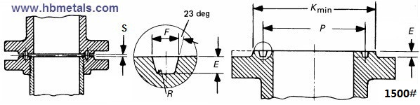
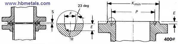
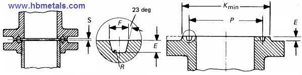
Ring Joint Facings for ASME B16.5 Flanges Classified by Classes
2. All dimensions are provided in mm and inch unit. The depth of the groove, E, shall be furnished with the same dimension as the height of the raised portion. The groove number of ring joint facings for class 1500 shall match the type R ring gaskets manufactured to ASME B16.20.
Ring Joint Facings for ASME B16.5 Flanges Classified by Classes
2. All dimensions are provided in mm and inch unit. The depth of the groove, E, shall be furnished with the same dimension as the height of the raised portion. The groove number of ring joint facings for class 900 shall match the type R ring gaskets manufactured to ASME B16.20.
Ring Joint Facings for ASME B16.5 Flanges Classified by Classes
2. All dimensions are provided in mm and inch unit. The depth of the groove, E, shall be furnished with the same dimension as the height of the raised portion. The groove number of ring joint facings for class 600 shall match the type R ring gaskets manufactured to ASME B16.20.
Ring Joint Facings for ASME B16.5 Flanges Classified by Classes
2. All dimensions are provided in mm and inch unit. The depth of the groove, E, shall be furnished with the same dimension as the height of the raised portion. The groove number of ring joint facings for class 400 shall match the type R ring gaskets manufactured to ASME B16.20.
Ring Joint Facings for ASME B16.5 Flanges Classified by Classes
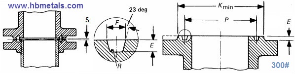
1. Technical drawings of ring joint facings for Class 300 ASME B16.5 Flanges.
The drawing of ring joint facings for Class 300 ASME B16.5 flanges.
2. Dimensions of ring joint facings for Class 300 Flange Joints and Groove.
NPS
Groove Number
P
inch
mm
E
inch
mm
F
inch
mm
R
inch
mm
K
inch
mm
S
inch
mm
1/2"
R11
1.344
34.14
0.219
5.54
0.281
7.14
0.03
0.8
2.00
51.0
0.12
3
3/4"
R13
1.688
42.88
0.250
6.35
0.344
8.74
0.03
0.8
2.50
63.5
0.16
4
1"
R16
2.000
50.80
0.250
6.35
0.344
8.74
0.03
0.8
2.75
70.0
0.16
4
1 1/4"
R18
2.375
60.33
0.250
6.35
0.344
8.74
0.03
0.8
3.12
79.5
0.16
4
1 1/2"
R20
2.688
68.27
0.250
6.35
0.344
8.74
0.03
0.8
3.56
90.5
0.16
4
2"
R23
3.250
82.55
0.312
7.92
0.469
11.91
0.03
0.8
4.25
108
0.22
6
2 1/2"
R26
4.000
101.60
0.312
7.92
0.469
11.91
0.03
0.8
5.00
127
0.22
6
3 1/2"
R34
5.188
131.78
0.312
7.92
0.469
11.91
0.03
0.8
6.25
159
0.22
6
4"
R37
5.875
149.23
0.312
7.92
0.469
11.91
0.03
0.8
6.88
175
0.22
6
5"
R41
7.125
180.98
0.312
7.92
0.469
11.91
0.03
0.8
8.25
210
0.22
6
6"
R45
8.312
211.12
0.312
7.92
0.469
11.91
0.03
0.8
9.50
241
0.22
6
8"
R49
10.625
269.88
0.312
7.92
0.469
11.91
0.03
0.8
11.88
302
0.22
6
10"
R53
12.750
323.85
0.312
7.92
0.469
11.91
0.03
0.8
14.00
356
0.22
6
12"
R57
15.000
381.00
0.312
7.92
0.469
11.91
0.03
0.8
16.25
413
0.22
6
14"
R61
15.625
419.10
0.312
7.92
0.469
11.91
0.03
0.8
18.00
457
0.22
6
16"
R65
17.875
469.90
0.312
7.92
0.469
11.91
0.03
0.8
20.00
508
0.22
6
18"
R69
20.375
533.40
0.312
7.92
0.469
11.91
0.03
0.8
22.62
575
0.22
6
20"
R73
22.000
584.20
0.375
9.53
0.531
13.49
0.06
1.5
25.00
635
0.22
6
24"
R77
26.500
692.15
0.438
11.13
0.656
16.66
0.06
1.5
29.50
749
0.25
6
1. NPS denotes nominal pipe size, P – pitch diameter, E – depth of the groove & height of the raised portion, F – top width of the groove, R – radius at bottom, K – diameter of raised portion, S – approximate distance between flanges. The 300# RTJ flange facings can be applied to various flange types including welding neck flange class 300, slip on flange 300#, Blind flange 300lb, etc.
2. All dimensions are provided in mm and inch unit. The depth of the groove, E, shall be furnished with the same dimension as the height of the raised portion. The groove number of ring joint facings for class 300 shall match the type R ring gaskets manufactured to ASME B16.20.
Ring Joint Facings for ASME B16.5 Flanges Classified by Classes
1. Technical drawings of ring joint facings for Class 150 ASME B16.5 Flanges.
The typical drawing of ring joint facings for Class 150 flanges manufactured to ASME B16.5.
2. Dimensions of ring joint facings for Class 150 Flange Joints and Groove.
NPS
Groove Number
P
inch
mm
E
inch
mm
F
inch
mm
R
inch
mm
K
inch
mm
S
inch
mm
1"
R15
1.875
47.63
0.250
6.35
0.344
8.74
0.03
0.8
2.5
63.5
0.16
4
1-1/4"
R17
2.250
57.15
0.250
6.35
0.344
8.74
0.03
0.8
2.88
73.0
0.16
4
1-1/2"
R19
2.562
65.07
0.250
6.35
0.344
8.74
0.03
0.8
3.25
82.5
0.16
4
2"
R22
3.250
82.55
0.250
6.35
0.344
8.74
0.03
0.8
4.00
102
0.16
4
2-1/2"
R25
4.000
101.6
0.250
6.35
0.344
8.74
0.03
0.8
4.75
121
0.16
4
3"
R29
4.500
114.3
0.250
6.35
0.344
8.74
0.03
0.8
5.25
133
0.16
4
3-1/2"
R33
5.188
131.78
0.250
6.35
0.344
8.74
0.03
0.8
6.06
154
0.16
4
4"
R36
5.875
149.23
0.250
6.35
0.344
8.74
0.03
0.8
6.75
171
0.16
4
5"
R40
6.750
171.45
0.250
6.35
0.344
8.74
0.03
0.8
7.62
194
0.16
4
6"
R43
7.625
193.68
0.250
6.35
0.344
8.74
0.03
0.8
8.62
219
0.16
4
8"
R48
9.750
247.65
0.250
6.35
0.344
8.74
0.03
0.8
10.75
273
0.16
4
10"
R52
12.000
304.80
0.250
6.35
0.344
8.74
0.03
0.8
13.00
330
0.16
4
12"
R56
15.000
381.00
0.250
6.35
0.344
8.74
0.03
0.8
16.00
406
0.16
4
14"
R59
15.625
396.88
0.250
6.35
0.344
8.74
0.03
0.8
16.75
425
0.12
3
16"
R64
17.875
454.03
0.250
6.35
0.344
8.74
0.03
0.8
19.00
483
0.12
3
18"
R68
20.375
517.53
0.250
6.35
0.344
8.74
0.03
0.8
21.50
546
0.12
3
20"
R72
22.000
558.80
0.250
6.35
0.344
8.74
0.03
0.8
23.50
597
0.12
3
24"
R76
26.500
673.10
0.250
6.35
0.344
8.74
0.03
0.8
28.00
711
0.12
3
1. NPS denotes nominal pipe size, P – pitch diameter, E – depth of the groove & height of the raised portion, F – top width of the groove, R – radius at bottom, K – diameter of raised portion, S – approximate distance between flanges. The 150# RTJ flange facings can be applied to various flange types including welding neck flange class 150, slip on flange 150#, Blind flange 150lb, etc.
2. All dimensions are provided in mm and inch unit. The depth of the groove, E, shall be furnished with the same dimension as the height of the raised portion. The groove number of ring joint facings for class 150 shall match the type R ring gaskets manufactured to ASME B16.20.
Ring Joint Facings for ASME B16.5 Flanges Classified by Classes
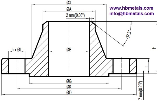
Technical drawing of ASME B16.5 weld neck flanges 400LB.
The typical drawing of weld neck flanges 400LB with raised face according to ASME B16.5.
Dimension and weight specifications of ASME B16.5 Weld Neck flanges 400LB.
NPS
D
inch
mm
K
inch
mm
G
inch
mm
B
inch
mm
A
inch
mm
X
inch
mm
n
L
inch
t
inch
mm
H
inch
mm
Wt.
lbs
kgs
1/2"
3.75
95
2.62
66.7
1.38
34.9
-
0.84
21.3
1.50
38
4
5/8
0.56
14.3
2.06
52
1.90
0.87
3/4"
4.62
115
3.25
82.6
1.69
42.9
-
1.05
26.7
1.88
48
4
3/4
0.62
15.9
2.25
57
3.20
1.45
1"
4.88
125
3.50
88.9
2.00
50.8
-
1.32
33.4
2.12
54
4
3/4
0.69
17.5
2.44
62
3.90
1.76
1-1/4"
5.25
135
3.88
98.4
2.50
63.5
-
1.66
42.2
2.50
64
4
3/4
0.81
20.7
2.62
67
5.50
2.49
1-1/2"
6.12
155
4.50
114.3
2.88
73.0
-
1.90
48.3
2.75
70
4
7/8
0.88
22.3
2.75
70
7.70
3.49
2"
6.50
165
5.00
127.0
3.62
92.1
-
2.39
60.3
3.31
84
8
3/4
1.00
25.4
2.88
73
9.60
4.36
2-1/2"
7.50
190
5.88
149.2
4.12
104.8
-
2.88
73.0
3.94
100
8
7/8
1.12
28.6
3.12
79
14.2
6.43
3"
8.25
210
6.62
168.3
5.00
127.0
-
3.50
88.9
4.62
117
8
7/8
1.25
31.8
3.25
83
18.8
8.53
3-1/2"
9.00
230
7.25
184.2
5.50
139.7
-
4.00
101.6
5.25
133
8
1
1.38
35.0
3.38
86
23.6
10.7
4"
10.00
255
7.88
200.0
6.19
157.2
-
4.50
114.3
5.75
146
8
1
1.38
35.0
3.50
89
28.2
12.8
5"
11.00
280
9.25
235.0
7.31
185.7
-
5.56
141.3
7.00
178
8
1
1.50
38.1
4.00
102
37.2
16.9
6"
12.50
320
10.62
269.9
8.50
215.9
-
6.63
168.3
8.12
206
12
1
1.62
41.3
4.06
103
48.5
22.0
8"
15.00
380
13.00
330.0
10.62
269.9
-
8.63
219.1
10.25
260
12
1-1/8
1.88
47.7
4.62
117
76.4
34.7
10"
17.50
445
15.25
387.4
12.75
323.8
-
10.75
273.0
12.62
321
16
1-1/4
2.12
54.0
4.88
124
107
48.5
12“
20.50
520
17.75
450.8
15.00
381.0
-
12.75
323.8
14.75
375
16
1-3/8
2.25
57.2
5.38
137
153
69.6
14”
23.00
585
20.25
514.4
16.25
412.8
-
14.00
355.6
16.75
425
20
1-3/8
2.38
60.4
5.88
149
210
95.5
16“
25.50
650
22.50
571.5
18.50
469.9
-
16.00
406.4
19.00
483
20
1-1/2
2.50
63.5
6.00
152
260
118
18”
28.00
710
24.75
628.6
21.00
533.4
-
18.00
457.0
21.00
533
24
1-1/2
2.62
66.7
6.50
165
319
145
20“
30.50
775
27.00
685.8
23.00
584.2
-
20.00
508.0
23.12
587
24
1-5/8
2.75
69.9
6.62
168
383
174
24”
36.00
915
32.00
812.8
27.25
692.2
-
24.00
610.0
27.62
702
24
1-7/8
3.00
76.2
6.88
175
553
251
(1) 400LB refers to Class 400 which is one of the pressure ratings stipulated by ASME B16.5. For dimensional denotation of D, K, G, t, H, A, X, n and L, please reference WN flanges Class 150. The welding end and flange facing(usually RF or RTJ) shall be furnished in accordance with ASME B16.5.
(2) The raised face of weld neck flanges 400LB shall be furnished with a height of 7 mm. All dimensions are provided in both metric and imperial units except for the bolt hole dimensions. Each value of the two systems shall be used separately. The bore diameter B shall be specified by the purchaser. Sizes from NPS 1/2 to NPS 3-1/2 has exactly the same dimensions as that of weld neck flanges 600LB (Class 600).
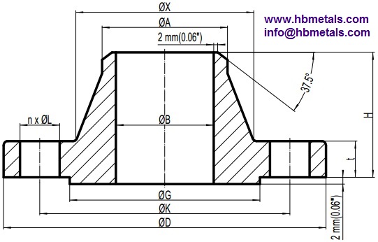
Technical drawing of ASME B16.5 weld neck flanges 300LB.
The typical drawing for WN RF flanges Class 300 according to ASME B16.5.
Dimension and weight specifications of ASME B16.5 Weld Neck flanges 300LB.
NPS
D
inch
mm
K
inch
mm
G
inch
mm
B
inch
mm
A
inch
mm
X
inch
mm
n
L
inch
t
inch
mm
H
inch
mm
Wt.
lbs
kgs
1/2"
3.75
95
2.62
66.7
1.38
34.9
0.62
15.8
0.84
21.3
1.50
38
4
5/8
0.50
12.7
2.00
51
1.70
0.75
3/4"
4.62
115
3.25
82.6
1.69
42.9
0.82
20.9
1.05
26.7
1.88
48
4
3/4
0.56
14.3
2.19
56
2.82
1.27
1"
4.88
125
3.50
88.9
2.00
50.8
1.05
26.6
1.32
33.4
2.12
54
4
3/4
0.62
15.9
2.38
60
3.50
1.52
1-1/4"
5.25
135
3.88
98.4
2.50
63.5
1.38
35.1
1.66
42.2
2.50
64
4
3/4
0.69
17.5
2.50
64
4.50
2.03
1-1/2"
6.12
155
4.50
114.3
2.88
73.0
1.61
40.9
1.90
48.3
2.75
70
4
7/8
0.75
19.1
2.63
67
6.40
2.89
2"
6.50
165
5.00
127.0
3.62
92.1
2.07
52.5
2.38
60.3
3.31
84
8
3/4
0.81
20.7
2.69
68
7.50
3.40
2-1/2"
7.50
190
5.88
149.2
4.12
104.8
2.47
62.7
2.88
73.0
3.94
100
8
7/8
0.94
23.9
2.94
75
11.40
5.17
3“
8.25
210
6.62
168.3
5.00
127.0
3.07
77.9
3.50
88.9
4.62
117
8
7/8
1.06
27.0
3.06
78
15.3
6.93
3-1/2”
9.00
230
7.25
184.2
5.50
139.7
3.55
90.1
4.00
101.6
5.25
133
8
7/8
1.12
28.6
3.13
79
19.1
8.67
4“
10.00
255
7.88
200
6.19
157.2
4.03
102.3
4.50
114.3
5.75
146
8
7/8
1.19
30.2
3.32
84
24.7
11.2
5”
11.00
280
9.25
235.0
7.31
185.7
5.05
128.2
5.56
141.3
7.00
178
8
7/8
1.31
33.4
3.82
97
33.3
15.1
6“
12.50
320
10.62
269.9
8.50
215.9
6.07
154.1
6.63
168.3
8.12
206
12
7/8
1.38
35.0
3.82
97
42.4
19.1
8”
15.00
380
13.00
330.2
10.62
269.9
7.98
202.7
8.63
219.1
10.25
260
12
1
1.56
39.7
4.32
110
65.9
29.9
10“
17.50
445
15.25
387.4
12.75
323.8
10.02
254.6
10.75
273.0
12.62
321
16
1-1/8
1.81
46.1
4.56
116
94.1
42.7
12”
20.50
520
17.75
450.8
15.00
381.0
12.00
304.8
12.75
323.8
14.75
375
16
1-1/4
1.94
49.3
5.06
129
136.2
61.9
14“
23.00
585
20.25
514.4
16.25
412.8
-
14.00
355.6
16.75
425
20
1-1/4
2.06
52.4
5.56
141
189
85.8
16”
25.50
650
22.50
571.5
18.50
469.9
-
16.00
406.4
19.00
483
20
1-3/8
2.19
55.6
5.69
144
234
106
18“
28.00
710
24.75
628.6
21.00
533.4
-
18.00
457.0
21.00
533
24
1-3/8
2.31
58.8
6.19
157
289
131
20”
30.50
775
27.00
685.8
23.00
584.2
-
20.00
508.0
23.12
587
24
1-3/8
2.44
62.0
6.32
160
348
158
24“
36.00
915
32.00
812.8
27.25
692.2
-
24.00
610.0
27.62
702
24
1-5/8
2.69
68.3
6.56
167
507
230
(1) 300LB refers to Class 300 which is one of the pressure ratings stipulated by ASME B16.5. Dimensions D, B, t and H refer to the basic flange dimensions: D – outside diameter of flange, B – bore diameter of weld neck flange, t – minimum thickness of flange, H – length through hub of weld neck flange. n, L and K refer to the bolting drilling dimensions of flange: n – number of bolts, L – diameter of bolt holes, K – diameter of bolt circle. G denotes the outside diameter of raised face. A and X are dimensions associated with the hub: A – diameter at the top of hub, X – diameter at the root of hub. A is the same as the nominal outside diameter of the pipe connected to the flange.
(2) Usually two types of welding ends can be furnished according to different wall thickness of the pipe. The bore diameters of weld neck flanges 300LB correspond to the inside diameters of pipe as given in ASME B36.10 for standard(STD) wall pipe. Thickness of standard wall is the same as SCH40 in sizes 10″ and smaller. These bore sizes are furnished unless otherwise specified by the purchaser. Besides, bore diameters of 14″ and larger shall be specified by the purchaser. Ring joint facing (RTJ) is also available upon request. All tolerances shall be in accordance with ASME B16.5.
(3) The raised-face length(2 mm) of Weld neck flanges 300LB is the same as that of weld neck flanges 150LB. All dimensions are provided in both metric and imperial units except for the bolt hole dimensions. Each value of the two systems shall be used separately.
Technical drawing of ASME B16.5 weld neck flanges 150LB.
The typical drawing of weld neck flanges 150LB with raised face.
Dimension and weight specifications of ASME B16.5 Weld Neck flanges 150LB.
NPS
D
inch
mm
K
inch
mm
G
inch
mm
B
inch
mm
A
inch
mm
X
inch
mm
n
L
inch
t
inch
mm
H
inch
mm
Wt.
lbs
kgs
1/2"
3.50
90
2.38
60.3
1.38
34.9
0.62
15.8
0.84
21.3
1.19
30
4
5/8
0.38
9.6
1.81
46
1.10
0.48
3/4"
3.88
100
2.75
69.9
1.69
42.9
0.82
20.9
1.05
26.7
1.50
38
4
5/8
0.44
11.2
2.00
51
1.62
0.71
1"
4.25
110
3.12
79.4
2.00
50.8
1.05
26.6
1.32
33.4
1.94
49
4
5/8
0.50
12.7
2.12
54
2.21
1.02
1-1/4"
4.62
115
3.50
88.9
2.50
63.5
1.38
35.1
1.66
42.2
2.31
59
4
5/8
0.56
14.3
2.19
56
2.90
1.33
1-1/2"
5.00
125
3.88
98.4
2.88
73.0
1.61
40.9
1.90
48.3
2.56
65
4
5/8
0.62
15.9
2.38
60
3.82
1.75
2"
6.00
150
4.75
120.7
3.62
92.1
2.07
52.5
2.38
60.3
3.06
78
4
3/4
0.69
17.5
2.44
62
5.70
2.58
2-1/2"
7.00
180
5.50
139.7
4.12
104.8
2.47
62.7
2.88
73.0
3.56
90
4
3/4
0.81
20.7
2.69
68
9.11
4.13
3"
7.50
190
6.00
152.4
5.00
127.0
3.07
77.9
3.50
88.9
4.25
108
4
3/4
0.88
22.3
2.69
68
10.80
4.92
3-1/2"
8.50
215
7.00
177.8
5.50
139.7
3.55
90.1
4.00
101.6
4.81
122
8
3/4
0.88
22.3
2.75
70
13.40
6.08
4"
9.00
230
7.50
190.5
6.19
157.2
4.03
102.3
4.50
114.3
5.31
135
8
3/4
0.88
22.3
2.94
75
15.10
6.84
5"
10.00
255
8.50
215.9
7.31
185.7
5.05
128.2
5.56
141.3
6.44
164
8
7/8
0.88
22.3
3.44
87
18.90
8.56
6"
11.00
280
9.50
241.3
8.50
215.9
6.07
154.1
6.63
168.3
7.56
192
8
7/8
0.94
23.9
3.44
87
23.30
10.60
8"
13.50
345
11.75
298.5
10.62
269.9
7.98
202.7
8.63
219.1
9.69
246
8
7/8
1.06
27.0
3.94
100
38.80
17.70
10"
16.00
405
14.25
362.0
12.75
323.8
10.02
254.6
10.75
273.0
12.00
305
12
1
1.12
28.6
3.94
100
53.00
24.00
12"
19.00
485
17.00
431.8
15.00
381.0
12.00
304.8
12.75
323.8
14.38
365
12
1
1.19
30.2
4.44
113
80.40
36.50
14"
21.00
535
18.75
476.3
16.25
412.8
-
14.00
355.6
15.75
400
12
1-1/8
1.31
33.4
4.94
125
107.0
48.40
16"
23.50
595
21.25
539.8
18.50
469.9
-
16.00
406.4
18.00
457
16
1-1/8
1.38
35.0
4.94
125
134.0
60.60
18"
25.00
635
22.75
577.9
21.00
533.4
-
18.00
457.0
19.88
505
16
1-1/4
1.50
38.1
5.44
138
151.2
68.4
20"
27.50
700
25.00
635.0
23.00
584.2
-
20.00
508.0
22.00
559
20
1-1/4
1.62
41.3
5.64
143
187.00
84.82
24"
32.00
815
29.50
749.3
27.25
692.2
-
24.00
610.0
26.12
663
20
1-3/8
1.81
46.1
5.94
151
253.0
115.0
(1) 150LB refers to Class 150 which is one of the pressure ratings stipulated by ASME B16.5. Dimensions D, B, t and H refer to the basic flange dimensions: D – outside diameter of flange, B – bore diameter of weld neck flange, t – minimum thickness of flange, H – length through hub of weld neck flange. n, L and K refer to the bolting drilling dimensions of flange: n – number of bolts, L – diameter of bolt holes, K – diameter of bolt circle. G denotes the outside diameter of raised face. A and X are dimensions associated with the hub: A – diameter at the top of hub, X – diameter at the root of hub. A is the same as the nominal outside diameter of the pipe connected to the flange.
(2) Usually two types of welding ends can be furnished according to different wall thickness of the pipe. The bore diameters of weld neck flanges 150LB correspond to the inside diameters of pipe as given in ASME B36.10 for standard(STD) wall pipe. Thickness of standard wall is the same as SCH40 in sizes 10″ and smaller. These bore sizes are furnished unless otherwise specified by the purchaser. Besides, bore diameters of 14″ and larger shall be specified by the purchaser. Ring joint facing (RTJ) is also available upon request. All tolerances shall be in accordance with ASME B16.5.
(3) All dimensions are provided in both metric and imperial units except for the bolt hole dimensions. Each value of the two systems shall be used separately.


