EN 10216-4 P255QL Seamless Steel Tube / Pipe

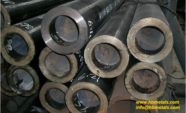
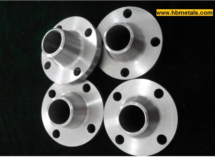
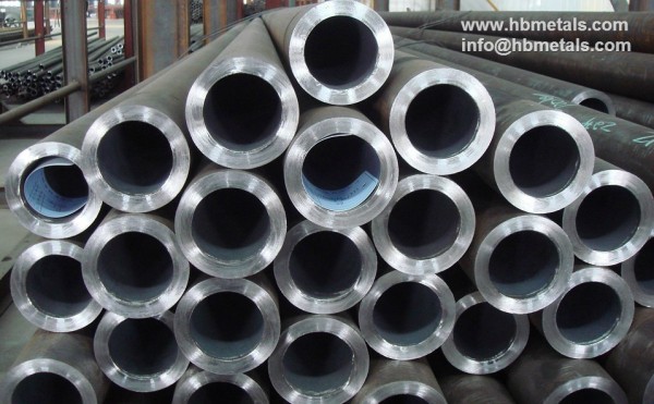
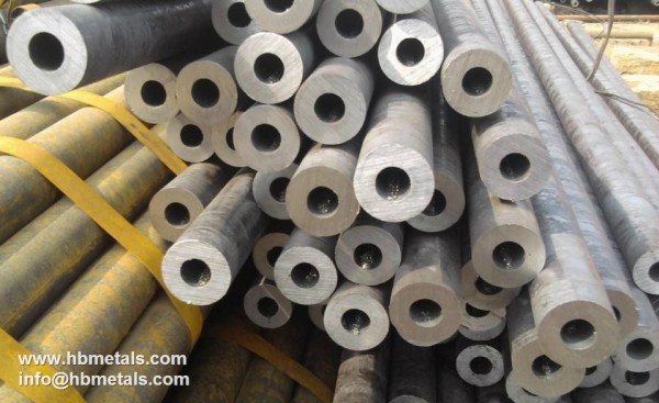
EN 10216-4 is the standard specification for seamless steel tubes for pressure purposes – Technical delivery conditions – Part 4: Non-alloy and alloy steel tubes with specified low temperature properties. P255QL, with a steel number of 1.0452, is one of the non-alloy quality steel grades designated by EN 10216-4. The EN 10216-4 P255QL seamless tubes are often used in services with a minimum temperature of -46°C.

en 10216-4 p255ql seamless tube 219.1x22.2
EN 1026-4 P255QL seamless pipes, O.D 219.1mm x 22.2mm(W.T). For a project in Liverpool, UK.
low temperature seamless pipes en 10216-4 76.1x17.5 p255ql
Low temperature seamless tubes EN 10216-4 O.D 76.1mm x 17.5mm Grade P255QL / 1.0452

Chemical composition of EN 10216-4 P255QL / 1.0452

ElementContent by mass, %
Carbon (C)≤0.17
Silicon (Si)≤0.35
Manganese (Mn)0.40~1.20
Phosphorous (P)≤0.025
Sulfur (S)≤0.020
Chromium (Cr)≤0.30
Nickel (Ni)≤0.30
Molybdenum (Mo)≤0.08
Aluminium (Al)≥0.020
Copper (Cu)≤0.30
Niobium (Nb)≤0.010
Titanium (Ti)≤0.040
Vanadium (V)≤0.02

Mechanical properties of EN 10216-4 P255QL / 1.0452

Steel NameSteel NumberYield Strength,
MPa
Tensile Strength,
MPa
Elongation A
Longitudinal, %
Elongation B
Transverse, %
P255QL1.0452≥255360~490≥23≥21

Heat treatment conditions

For low-temperature purpose, EN 10216-4 P255QL shall be fully killed. The capital letter “P” stands for pressure purposes; “255” indicates the minimum yield strength of 255 MPa; “Q” indicates the heat treatment as quenching and tempering; “L” indicates the use for low-temperature purposes.

Usually the seamless tube or pipe of grade P255QL shall be quenched and tempered. The quenching temperature(hardening temperature) shall be at 890°C to 930°C while tempering temperature is ranging from 600°C to 680°C.

16Mo3 / 1.5415 European Alloy Steels

16Mo3 Material

16Mo3, designated with steel number 1.5415, is an European (DIN EN) steel grade for alloy steels. The 16Mo3 material can be furnished in different product forms in accordance with relative EN standards. Generally speaking, 16Mo3 is a Cr-Mo alloy steel. The addition of molybdenum(Mo) not only improves the resistance to pitting corrosion but also significantly enhances creep strength at elevated temperatures. The chromium(Cr) improves the resistance to high-temperature hydrogen attack and graphitization.

(1) EN 10216-2: Seamless steel tubes for pressure purposes – Technical delivery conditions – Part 2: Non-alloy and alloy steel tubes with specified elevated temperature properties.

EN 10216-2 16Mo3 seamless pipes 323.8mm x 46mm 6m
EN 10216-2 16Mo3 seamless pipes for a power plant project in Czech, O.D=323.8mm, W.T=46mm L=6m.

(2) EN 10253-2: Butt welding pipe fittings – Part 2: Non-alloy and ferritic alloy steels with specific inspection requirements.

EN 10253-2 16Mo3 elbow 3d dn600 x 60mm type B bevelled ends
EN 10253-2 16Mo3 Elbow 3D 90° DN600 x 60mm Type B bevelled ends.

(3) EN 10222-2: Steel forgings for pressure purposes – Part 2: Ferritic and martensitic steels with specified elevated temperature properties(especially, referring to EN 1092-1 flanges.

(4) EN 10217-2: Welded steel tubes for pressure purposes – Technical delivery conditions – Part 2: Electric welded non-alloy and alloy steel tubes with specified elevated temperature properties.

(5) EN 10217-5: Welded steel tubes for pressure purposes – Technical delivery conditions – Part 5: Submerged arc welded non-alloy and alloy steel tubes with specified elevated temperature properties.

(6) EN 10028-2: Flat products(especially referring to steel plates) made of steels for pressure purposes. Part 2: Non-alloy and alloy steels with specified elevated temperature properties.

(7) EN 10273: Hot rolled weldable steel bars for pressure purposes with specified elevated temperature properties.

16Mo3 ASTM Equivalent

Since relative ASTM(ASME) standards are most widely utilized in pipeline design, sometimes it is necessary to find the decent ASTM / ASME equivalent for the EN 16Mo3 steel. As a rule of thumb, their correlations are shown in below data sheet:

16Mo3 MaterialASTM Equivalent
Butt Welding Pipe FittingsASTM A234 WP1
Seamless PipesASTM A335 P1
BarsASTM A217 WC1
Welded Pipe / PlatesASTM A204 Gr.A & Gr. B
Forgings(Flanges)ASTM A182 F1

Weight Calculation of Weld Neck Flanges

Weld Neck flanges, also know as “WN flanges” or “Welding Neck flanges”, are widely used in oil and gas industry, steam piping and offshore platforms. Sometimes, it is necessary to know the weight of a weld neck flange in piping design. Instead of querying the experimental data from flange manufacturers, theoretical weight can be calculated directly. The weight calculation of weld neck flanges is based on the geometrical or mathematical modeling of the flange.

The typical drawing of weld neck flanges

weight calculation of weld neck flanges
Mathematical Modeling for weight calculation of weld neck flanges

The typical drawing is for weld neck flanges in accordance with ASME B16.5. The welding end is furnished with beveling for wall thickness from 5 mm to 22 mm (inclusive). And the flange has raised face (RF).

All the dimensions are covered by the standard specification: H – the overall length through hub of weld neck flanges;  T – minimum thickness of the flange; t – the height of raised face(2mm for Class 150 and 300, 7mm for Class 400 600, 900, 1500 and 2500); D – outside diameter of the flange; K – diameter of bolt circle; G – outside diameter of the raised face; B – bore diameter of weld neck flanges which is in accordance with ASME B36.10; A – hub diameter at the beginning of chamfer of welding neck flanges; X- root diameter of the hub; n – number of bolts; L – diameter of bolt holes.

Mathematical modeling for weight calculation of weld neck flanges

As illustrated in above drawing, geometrically the weld neck flange can be divided into 4 parts.

Part I can be treated as a short length of pipe. According to ASME B16.5, the straight length is furnished in 10 mm. Hence the weight of Part I can be calculated by using the weight-calculation formula of pipe:
W1 = 0.0246615 * (A – Tk) * Tk * 0.01      T– wall thickness of the mating pipe.

Part II can be treated as a truncated cone deducted by a cylinder. Its weight can be calculated as:
W2 = {1/3 * π * (H – T – t – 0.01) * [(X/2)2 + (A/2)2 + X*A/4)] – 1/4 * π * B2 * (H – T – t – 0.01)} * ρ

Part III is a cylinder deducted by several small cylinders(bolt holes and bore):
W3 = 1/4 * π * (D2 – B2 – n*L2) * T * ρ

Part IV, the raised face, can be treated as a cylinder deducted by another cylinder(bore):
W4 = 1/4 * π * (G2 – B2) * t * ρ

The total weight of the weld neck flange is W = W1 + W2 + W3 + W4

Welding Ends for Weld Neck Flanges

According to ASME B16.5 and ASME B16.25, welding neck flanges can be furnished with two types of welding ends which are illustrated in below figures:

Welding ends of weld neck flanges thin
The welding ends of weld neck flanges for wall thickness 5 mm < t ≤ 22 mm.
welding ends of wn flange thick
The welding end of weld neck flanges for wall thickness t > 22mm.

Dimension A denotes nominal outside diameter of the pipe while B denotes nominal inside diameter of the pipe. The t and X respectively represent nominal wall thickness and the diameter of hub of the weld neck flange.

When the thickness of the hub at the bevel is greater than that of the pipe to which the welding neck flange is joined and the additional thickness is provided on the outside diameter, a taper weld having a slope not exceeding 1 to 3 maybe used, or alternatively, the greater outside diameter may be tapered at the same maximum slope or less, from a point on the welding bevel equal to the outside diameter of the mating pipe. Similarly, when the greater thickness is provided on the inside of the flange, it shall be taper-bored from the welding end at a slope not exceeding 1/3. When ASME B16.5 flanges are intended for services with light wall, higher strength pipe, the thickness of the hub at the bevel may be greater than that of the pipe to which the flange is joined. Under these conditions, a single taper hub may be provided. The additional thickness may be provided on either inside or outside or partially on each side, but the total additional thickness shall not exceed 1.5 times the nominal wall thickness of intended mating pipe.

Besides, the hub transition from the A diameter to the X diameter shall fall within the maximum and minimum envelope outlined by the 1:3 max slope and solid line. The 6-mm length is the minimum dimension applies only to the solid line configuration.

ASTM A182 F5 Flanges

ASTM A182 F5 flanges are forged flanges manufactured from a chromium-molybdenum low alloy steel know as 5Cr-0.5Mo with a UNS designation of K41545. They are widely utilized in pressure high-temperature services such as oil refineries, chemical and petrochemical industries, power plant piping, heat exchangers, and various pressure vessels.

WN RF 4" 300LB SCH40 ASTM A182 F5 flanges
4″ WN Flange RF, 300LB SCH40, ASTM A182 Gr. F5

Chemical composition of ASTM A182 Gr. F5

CMnPSSiNiCrMo
0.15 max0.30~0.600.030 max0.030 max0.50 max0.50 max4.0~6.00.44~0.65
The chromium (Cr) added in F5 not only increases resistance to abrasion and corrosion but also improves resistance to high-temperature hydrogen attack and graphitization. The molybdenum (Mo) content is acting as a grain refiner which enhances creep resistance and high-temperature strength. It also improves resistance to pitting corrosion in many environments. The creep strength of chromium-molybdenum low alloy is derived mainly from two sources: solid-solution strengthening of the matrix ferrite by  carbon, molybdenum and chromium as well as precipitation hardening by carbides. As a result, the creep strength (for 1% elongation in 105 hours) of A182 Grade F5 may reach approx. 170 MPa at 450 °C.

PMI test for A182 F5 flanges

Mechanical requirements and heat treatment.

Tensile Strength,
min, ksi [MPa]
Yield Strength,
min, kis [MPa]
Elongation,
min, %
Reduction of
Area, min, %
Brinell Hardness,
HBW
70 [485]40 [275]2035143~217
According to ASME B16.5, pipe flanges manufactured from A812 Gr. F5 material shall be normalized and tempered at a temperature higher than 955 °C (1750 °F). The material is permissible but not recommended for prolonged use above 590 °C.

Pressure-Temperature ratings for ASTM A182 F5 flanges.

Temp. °CClass 150Class 300Class 400Class 600Class 900Class 1500Class 2500
-29~3819.851.768.9103.4155.1258.6430.9
5019.551.568.7103.0154.5257.5429.2
10017.750.467.3100.9151.3252.2420.4
15015.848.264.296.4144.5240.9401.5
20013.846.361.792.5138.8231.3385.6
25012.144.859.889.6134.5224.1373.5
30010.242.957.085.7128.6214.4357.1
3259.341.455.082.6124.0206.6344.3
3508.440.353.680.4120.7201.1335.3
3757.438.951.677.6116.5194.1323.2
4006.536.548.973.3109.8183.1304.9
4255.535.246.570.0105.1175.1291.6
4504.633.745.167.7101.4169.0281.8
4753.727.937.155.783.6139.3232.1
5002.821.428.542.864.1106.9178.2
5381.413.718.327.441.168.6114.3
550-12.016.124.136.160.2100.4
575-8.811.717.626.444.073.4
600-6.18.112.118.230.350.4
625-4.05.38.012.020.033.3
650-2.43.24.77.111.819.7

ASME B16.5 Flange facing and Facing Finish

Various types of flange facing.

According to ASME B16.5, there are several types of end flange facing which shall be calculated and selected carefully to ensure a leak-free seal.

End Flange Facing 01
End Flange Facings 01
End Flange Facing 02
End Flange Facings 02

Figures A and B show the most common flange facing of raised face. 2 mm raised face is regularly furnished on Class 150 and Class 300 while 7 mm raised face is furnished on Class 400, Class 600, Class 900, Class 1500 and Class 2500. Figures C, D, E, F, G, H respectively illustrate the facing type of large or small male face, large or small female face, small male face(on end of pipe), small female face(on end of pipe), large or small tongue face, and large or small groove face. Figure I is the typical drawing of ring joint face which is also a prevalent flange connection requiring a metallic ring either in oval or octagonal shape. In the case of flanges having raised face, tongue, or male face, the minimum flange thickness tf, shall be provided, and then the raised face, tongue or male face shall be added thereto. For flanges that have a ring joint, groove, or female face, the minimum flange thickness tf shall first be provided and then sufficient thickness added thereto so that the bottom of the ring joint groove, or the contact face of the groove or female face, is in the same plane as the flange edge of a full thickness flange.

Lapped Joint with Stub Ends

Flat faces are usually used in cast iron flanges such as AWWA flanges in water supply service. However, lapped joint flanges shall be furnished with flat face (FF) as illustrated in figure G and K. The stub ends can be provided with raised face or ring joint face in similar function.

Surface finishes of flange facing.

The raised face or flat face shall be furnished with a serrated concentric or serrated spiral finish having a resultant surface roughness from 3.2μm to 6.3μm. The cutting tool employed should have an approximate 1.5 mm or larger radius, and there should be from 1.8 grooves/ mm through 2.2 grooves/ mm. The side wall surface roughness of the ring-joint gasket groove shall not exceed 1.6μm. For groove, tongue and small male and female, the gasket contact surface finish shall not exceed 3.2μm roughness.

Incoloy 800 Flanges (ASTM B564 UNS N08800)

1. General Introduction

Incoloy 800 flanges (pipe flanges) refer to forged flanges manufactured to ASTM B564 according to the dimensional standards of ASME B16.5. Incoloy 800, also known as Alloy 800 or UNS N08800, is an iron-nickel-chromium alloy with good creep & stress-rupture strength and excellent resistance to oxidation, sulfurization and carburization in high-temperature services. It also resists corrosion by many aqueous environments. The forged Incoloy 800 flanges can be used in applications with temperatures up to 816°C while maintaining a stable, austenitic structure during prolonged exposure to high temperatures. The material is widely utilized in processing piping, heat exchangers, heating element sheathing, petrochemical pipeline(especially for heavy oil) and nuclear power plant, etc.

Incoloy 800 Flanges WN RTJ
Incoloy 800 weld neck flange, RTJ, API 6A.

2. Pressure-Temperature ratings for Incoloy 800 flanges

Temp. °CClass 150Class 300Class 400Class 600Class 900Class 1500Class 2500
-29~3819.049.666.299.3148.9248.2413.7
5018.748.865.197.6146.4244.0406.7
10017.545.660.891.2136.9228.1380.1
15015.844.058.788.0132.0219.9366.6
20013.842.857.185.6128.4214.0356.7
25012.141.755.783.5125.2208.7347.9
30010.240.854.481.6122.5204.1340.2
3259.340.353.880.6120.9201.6336.0
3508.439.853.079.5119.3198.8331.3
3757.438.951.677.6116.5194.1323.2
4006.536.548.973.3109.8183.1304.9
4255.535.246.570.0105.1175.1291.6
4504.633.745.167.7101.4169.0281.8
4753.731.742.363.495.1158.2263.9
5002.828.237.656.584.7140.9235.0
5381.425.233.450.075.2125.5208.9
550-25.033.349.874.8124.9208.0
575-24.031.947.971.8119.7199.5
600-21.628.642.964.2107.0178.5
625-18.324.336.654.991.2152.0
650-14.118.928.142.570.7117.7
675-10.313.720.530.851.385.6
700-5.67.411.116.727.846.3
725-4.05.48.112.120.133.6
750-3.04.06.19.115.125.2
775-2.53.34.97.412.420.6
800-2.22.94.36.510.818.0
816-1.92.53.85.79.515.8
*All the forged Alloy 800 flanges shall be annealed.

3. Chemical composition requirements for Incoloy 800 (UNS N08800).

Chemical Composition of Incoloy 800

ElementContent, %
Nickel (Ni)30.0~35.0
Copper (Cu)0.75 max
Iron (Fe)39.5 min
Manganese (Mn)1.5 max
Carbon (C)0.10 max
Silicon (Si)1.0 max
Sulfur (S)0.015 max
Chromium (Cr)19.0~23.0
Aluminum (Al)0.15~0.60
Titanium (Ti)0.15~0.60
*Chromium additions improve sulfidation resistance while aluminum and titanium allow strengthening through precipitation hardening (age hardening). Nickel content not only improves the fatigue strength and high-temperature performance(especially in reducing environments) but also inherently resists to reducing corrosion, both acid and alkali. Thus, Incoloy 800 has better resistance to reducing corrosion than common austenitic stainless steels.

4. Mechanical requirements for Incoloy 800 forgings.

Mechanical Properties of Incoloy 800

Tensile Strength, min
ksi (MPa)
Yield Strength, min
ksi (MPa)
Elongation min.
%
75 (517)30 (207)30
*The forgings shall take ultrasonic test or liquid penetration inspection. Liquid penetration inspection is not applicable to forgings with hot finished surface.

Basic Introduction to ASME B16.5 Flanges

What are ASME B16.5 flanges

ASME B16.5 is the standard specification for pipe flanges and flanged fittings from NPS 1/2 (1/2″) through NPS 24 (24″) covering materials, pressure-temperature ratings, dimensions, tolerances, marking & packaging, and testing methods. ASME B16.5 flanges are designated into seven pressure ratings including Class 150, 300, 400, 600, 900 and 1500 in sizes NPS 1/2 (1/2″) through NPS 24 (24″) and Class 2500 in sizes NPS 1/2 (1/2″) through NPS (12″). The pipe flanges can also be categorized according to its type as: welding neck (WN), slip on (SO), socket welding (SW), threaded (TH), blind (BL), long weld neck (LWN), and lapped joint (LJ). NPS, followed by a dimensionless number, is the designation for nominal flange size. It is related to the reference nominal diameter, DN, which is used in international standards. Their relationship is shown in following table: 

The Relationship between NPS and DN

NPSDN
1/215
3/420
125
1-1/432
1-1/240
250
2-1/265
380
3-1/290
4100
5125
6150
8200
10250
12300
14350
16400
18450
20500
24600

Material selection for ASME B16.5 flanges

The pipe flanges can be made from either cast or forged materials. Especially, plate material are only allowed for some certain unhubbed flanges such as blind, slip on plate or reducing plate flanges due to the consideration of plate-lamination flaws. HBMetals manufactures pipe flanges from a comprehensive range of materials covering carbon steel, alloy steel, stainless steel and special alloys:

(1) Carbon Steel: ASTM A105(N), ASTM A515, ASTM A516, ASTM A694, ASTM A350;
(2) Alloy Steel: ASTM A182 F1, F2, F5, F5a, F9, F91, F92, F11, F12, F21, F22;
(3) Stainless Steel: ASTM A182 F304(L), F316(L), F317(L), F321, F347, F348,
                                                    F51, F44, F904L, 254SMO;
(4) Special Alloys: Inconel 600, Inconel 625, Inconel 601, Inconel 718;
                              Hastelloy B, C-276, C-22; Incoloy 800 / 825;
                              Monel K-500, Monel 400, Monel 401, Monel 404;
                              Titanium; Aluminium, Cobalt, Niobium.

ASME B16.5 flanges in stock
ASME B16.5 flanges in stock.

ASTM A105 flanges

1. ASTM A105 forged carbon steel flanges.

ASTM A105 is the standard specification for carbon steel forgings for piping applications including flanges, fittings and valve parts, etc. According to ASME B16.5(Pipe Flange), this material is categorized into Group 1.1 which has the same pressure-temperature ratings as ASTM A216 Grade WCB, A515 Grade 70, A350 Grade LF2, A516 Grade 70, A350 Grade LF6 Class 1, A537 Class 1 and A350 Grade LF3. ASTM A105 flanges refer to forged carbon steel flanges for ambient and high temperature service in pressure systems.They can be manufactured to dimensional standards of ASME B16.5, ASME B16.47, MSS SP 44, API 605, BS 4504, EN1092-1 and L-005, etc. HBMetals keeps a large amount of flanges available in stock covering flange types of welding neck, slip on, socket welding, threaded, blind, slip on plate, long weld neck, orifice and lap joint, etc.

ASTM A105 flanges in various types
ASME B16.5 Flanges in A105 material(WN, SO, BL)

2. Chemical composition, mechanical properties and pressure-temperature ratings for ASTM A105 flanges.

Chemical Composition Requirements of ASTM A105

ElementComposition,%
Carbon (C)0.35max
Manganese (Mn)0.60–1.05
Phosphorus (P)0.035max
Sulfur (S)0.040max
Silicon (Si)0.10–0.35
Copper (Cu)0.40max
Nickel (Ni)0.40max
Chromium (Cr)0.30max
Molybdenum (Mo)0.12max
Vanadium (V)0.08max
*The sum of copper, nickel, chromium, molybdenum and vanadium shall not exceed 1.00% while the sum of chromium and molybdenum shall not exceed 0.32%. The carbon equivalent CE = C + Mn/6 + (Cr + Mo + V)/5 + (Ni + Cu)/15 shall be no larger than 0.47 based on heat analysis.

Mechanical Properties of ASTM A105

Mechanical PropertiesRequirements
Tensile strength,min,psi [MPa]70000 [485]
Yield strength,min,psi [MPa]36000 [250]
Elongation, min, %30
Reductionofarea,min,%30
Hardness,HB,max187
*Unless otherwise specified by the customer, heat treatment is not a mandatory requirement for 150LB and 300LB A105 flanges. However, flanges above Class 300 (Class 400, 600, 900, 1500, 2500) or custom-design special flanges shall be furnished with one of the following heat treatment: 1) annealing, 2) normalizing, 3) normalizing and tempering, 4) quenching and tempering.

Pressure-Temperature Ratings for ASTM A105 flanges

Temp. °CWorking Pressure by Classes, bar
15030040060090015002500
-29 ~ 3819.651.168.1102.1153.2255.3425.5
5019.250.166.8100.2150.4250.6417.7
10017.746.662.193.2139.8233.0388.3
15015.845.160.190.2135.2225.4375.6
20013.843.858.487.6131.4219.0365.0
25012.141.955.983.9125.8209.7349.5
30010.239.853.179.6119.5199.1331.8
3259.338.751.677.4116.1193.6322.6
3508.437.650.175.1112.7187.8313.0
3757.436.448.572.7109.1181.8303.1
4006.534.746.369.4104.2173.6289.3
4255.528.838.457.586.3143.8239.7
4504.623.030.746.069.0115.0191.7
4753.717.423.234.952.387.2145.3
5002.811.815.723.535.358.897.9
5381.45.97.911.817.729.549.2
*ASTM A105 flanges are not recommended for prolonged use above 425°C since upon prolonged exposure to temperature above 425°C, the carbide phase of steel may be converted to graphite causing brittleness problems.

If you have any inquiry, please feel free to contact our Metals-Piping Division for a quote:
Email: sales@metalspiping.com | Website: www.metalspiping.com

Pressure-Temperature Ratings For Inconel 600 Flanges

Inconel 600 flanges are forged flanges made from Inconel 600 forgings in accordance with ASTM B564. Inconel 600 is a nickel-chromium-iron alloy which has a nominal designation 72Ni-15Cr-8Fe as well as UNS N06600. These flanges(also called “Alloy 600 flanges”) are widely used in oil & gas projects and chemical processing industry due to its excellent resistance to oxidation at high temperatures and resistance to cracking corrosion and caustic corrosion. ASME B16.5 stipulates the pressure-temperature ratings for Inconel 600 flanges which should be furnished in the heat-treatment condition of anneal.

Temp., °CInconel 600 Flanges Working Pressures by Classes, bar
150 30040060090015002500
-29 ~ 3820.051.768.9103.4155.1258.6430.9
5019.551.768.9103.4155.1258.6430.9
10017.751.568.7103.0154.6257.6429.4
15015.850.366.8100.3150.6250.8418.2
20013.848.664.897.2145.8243.4405.4
25012.146.3061.792.7139.0231.8386.2
30010.242.957.085.7128.6214.4357.1
3259.341.455.082.6124.0206.6344.3
3508.440.353.680.4120.7201.1335.3
3757.438.951.677.6116.5194.1323.2
4006.536.548.973.3109.8183.1304.9
4255.535.246.570.0105.1175.1291.6
4504.633.745.167.7101.4169.0281.8
4753.731.742.363.495.1158.2263.9
5002.828.237.656.584.7140.9235.0
5381.416.522.133.149.682.7137.9
550-13.918.627.941.869.7116.2
575-9.412.618.928.347.278.6
600-6.68.913.319.933.255.3
625-5.16.810.315.425.742.8
650-4.76.39.514.223.639.4
Inconel 600 WN RF 2" 150LB SCH80
Inconel 600 Weld Neck Flange RF 2″ 150LB SCH80 supplied to US.