According to ASME B16.5 and ASME B16.25, welding neck flanges can be furnished with two types of welding ends which are illustrated in below figures:
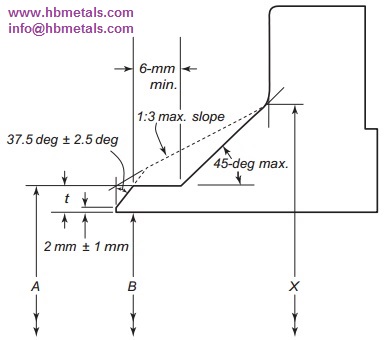
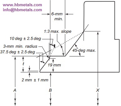
Dimension A denotes nominal outside diameter of the pipe while B denotes nominal inside diameter of the pipe. The t and X respectively represent nominal wall thickness and the diameter of hub of the weld neck flange.
When the thickness of the hub at the bevel is greater than that of the pipe to which the welding neck flange is joined and the additional thickness is provided on the outside diameter, a taper weld having a slope not exceeding 1 to 3 maybe used, or alternatively, the greater outside diameter may be tapered at the same maximum slope or less, from a point on the welding bevel equal to the outside diameter of the mating pipe. Similarly, when the greater thickness is provided on the inside of the flange, it shall be taper-bored from the welding end at a slope not exceeding 1/3. When ASME B16.5 flanges are intended for services with light wall, higher strength pipe, the thickness of the hub at the bevel may be greater than that of the pipe to which the flange is joined. Under these conditions, a single taper hub may be provided. The additional thickness may be provided on either inside or outside or partially on each side, but the total additional thickness shall not exceed 1.5 times the nominal wall thickness of intended mating pipe.
Besides, the hub transition from the A diameter to the X diameter shall fall within the maximum and minimum envelope outlined by the 1:3 max slope and solid line. The 6-mm length is the minimum dimension applies only to the solid line configuration.